

Troubleshooting
The multimeter is one of the most widely used and essential tools for diagnosing electrical issues in both residential and industrial systems. It allows technicians to safely test for voltage, current, resistance, and continuity in a wide range of applications. However, not all multimeters are created equally. The brand, model, and features of the device determine its capabilities and safe working limits. It is crucial to ensure the multimeter is rated appropriately for the voltage and current levels of the system being tested. Using a device outside of its rated range can pose serious risks, including electric shock or equipment damage.
Before using a multimeter, it's crucial to verify that it’s working correctly. This can be done by testing it on a known live circuit. Most multimeters require the user to manually select either AC or DC voltage based on the type of current being measured. Some modern models include an auto-detect feature, which simplifies the process by automatically identifying the type of voltage present.
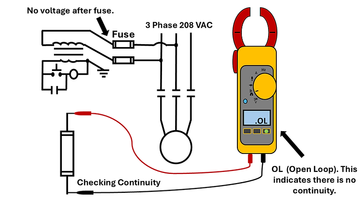
Resistance testing is another important function of a multimeter. When set to the Ohms setting, the device measures how easily electrical current can pass through a circuit. This is helpful when diagnosing open circuits or poor connections. Continuity, a related function, checks whether a circuit is complete. If there’s no path for current to flow, the multimeter may display “OL,” meaning “open loop.” Many models also emit a beep when continuity is present, providing a quick, audible confirmation for technicians.
Another useful feature is the ability to measure current or amperage. This can be done with either the probe leads or an amp clamp, depending on the multimeter’s design. Clamp meters are often used for measuring current in live AC circuits without the need to disconnect wiring. More advanced multimeters can measure both AC and DC current. When using an amp clamp, accuracy depends on proper wire placement. The wire must be centered within the clamp, and the clamp must be fully closed. Most clamp meters include guide markings to help users position the wire correctly.

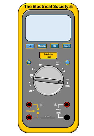
Insulation testers are essential diagnostic tools used to detect insulation breakdown or electrical leakage in a circuit. Their primary function is to apply a high DC voltage, sometimes up to 1,000 volts, through a conductor to evaluate the integrity of its insulation. If the insulation is compromised, current may leak from the conductor to surrounding materials or ground, indicating a potential fault. This type of testing is especially important during the installation of new wiring systems or equipment.
One common use of insulation testers is to verify that wire insulation was not damaged during the wire pulling process. Pulling wire through conduits or raceways can cause abrasion, cuts, or pressure-related damage to insulation. It's considered good practice to test insulation before pulling the wire to rule out factory defects, and again after installation to ensure no damage occurred during the process. Early testing can prevent future failures and costly downtime.
Insulation testers are also used in general troubleshooting. For example, they are helpful when checking the internal windings of electric motors. If the insulation within the windings has deteriorated or shorted, the tester will detect abnormal leakage between the windings or to the motor's grounded frame.
Because insulation testers apply high voltages, safety precautions are critical. The circuit under test must be fully de-energized, and all ends of the conductor not under test must be isolated or insulated. Applying the tester to a wire that is still connected to sensitive equipment, like breakers or electronic devices, can result in permanent damage. When performing tests, technicians typically check both phase-to-ground and phase-to-phase insulation resistance to ensure that the conductors are properly isolated from each other and from ground.
Rotation checkers are valuable tools used in the field of electrical troubleshooting, especially when working with three-phase motors. These devices are designed to help technicians determine the direction a motor will rotate before it is powered on. Ensuring proper rotation is crucial in many industrial and mechanical systems, where motors must turn in a specific direction to perform their intended function. If a motor spins in the wrong direction, it can cause serious damage to connected equipment, such as pumps, conveyors, or elevators.
The rotation checker itself is a compact and easy-to-use device. It works by connecting to the motor’s power leads, specifically, the three-phase wires. When properly connected, the rotation checker will display or indicate the expected direction of rotation. This allows technicians to make any necessary adjustments to the wiring before energizing the circuit.
Before using a rotation checker, safety must always come first. All work should follow Lockout/Tagout (LOTO) procedures to ensure the motor cannot be energized while being tested. This prevents potential injuries from moving parts or electrical shock.
To operate the rotation checker, technicians should first identify the correct motor leads by referring to the wiring diagram provided on the motor’s junction box or nameplate. The rotation checker’s probes are then connected to the labeled phase wires (typically L1, L2, and L3). Once all connections are secure, the tester can be powered on. The device will then indicate whether the current phase sequence will result in a clockwise or counterclockwise rotation. If the direction is incorrect, switching any two of the three-phase wires will reverse the rotation.

Phase identification keeps installations safe and organized. Getting these wrong can cause serious issues during maintenance or troubleshooting. Proper labeling and following the standard phase sequence help ensure reliability and safety on every job site.

To learn more about troubleshooting and common electrical issues, check out the TES Electrical Guidebook!